Spacecraft
After Mariner 10’s visits to Mercury, the space science and engineering communities yearned for a longer and more detailed look at the innermost planet – but that closer look, ideally from orbit, presented formidable technical obstacles. A Mercury orbiter would have to be tough, with enough protection to withstand searing sunlight and roasting heat bouncing back from the planet below. The spacecraft would need to be lightweight, since most of its mass would be fuel to fire its rockets to slow the spacecraft down enough to be captured by Mercury’s gravity. And the probe would have to be sufficiently compact to be launched on a conventional and cost-effective rocket. Designed and built by the Johns Hopkins University Applied Physics Laboratory – with contributions from research institutions and companies around the world – the MESSENGER spacecraft tackled each of these challenges and was the first spacecraft to orbit Mercury.
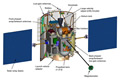
Spacecraft Overview
Thermal Design
While orbiting Mercury, MESSENGER “felt” significantly hotter than spacecraft that orbit Earth. This is because Mercury’s elongated orbit swings the planet to within 46 million kilometers (29 million miles) of the Sun, or about two-thirds closer to the Sun than Earth. As a result, the Sun shines up to 11 times brighter at Mercury than we see from our own planet.
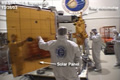
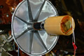
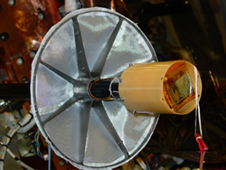
MESSENGER’s first line of thermal defense was a heat-resistant and highly reflective sunshade, fixed on a titanium frame to the front of the spacecraft. Measuring about 2.5 meters (8 feet) tall and 2 meters (6 feet) across, the thin shade had front and back layers of Nextel ceramic cloth – the same material that protects sections of the Space Shuttle – surrounding several inner layers of Kapton plastic insulation. While temperatures on the front of the shade were predicted to reach 370° C (about 700° F) when Mercury was closest to the Sun, behind it the spacecraft was designed to operate at room temperature, around 20° C (about 70° F). Multilayered insulation covered most of the spacecraft.
Radiators and diode (“one-way”) heat pipes were installed to carry heat away from the spacecraft body, and the science orbit was designed to limit MESSENGER’s exposure to heat re-radiating from the surface of Mercury. (MESSENGER only spent about 25 minutes of each 12-hour orbit crossing Mercury’s broiling surface at low altitude.) The combination of the sunshade, thermal blanketing, and heat-radiation system allowed the spacecraft to operate without special high-temperature electronics.
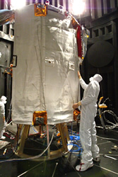
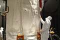
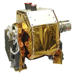
Inspection of MESSENGER’s sunshade prior to thermal vaccum testing
Power
Two single-sided solar panels were the spacecraft’s main source of electric power. To run MESSENGER’s systems and charge its 23-ampere-hour nickel-hydrogen battery, the panels, each about 1.5 meters (5 feet) by 1.65 meters (5.5 feet), supported between 385 and 485 watts of spacecraft load power during the cruise phase and 640 watts during the orbit at Mercury. The panels could have produced more than two kilowatts of power near Mercury, but to prevent stress on MESSENGER’s electronics, onboard power processors took in only what the spacecraft actually needed.
The custom-developed panels were two-thirds mirrors (called optical solar reflectors) and one-third triple-junction solar cells, which converted 28 percent of the sunlight hitting them into electricity. Each panel had two rows of mirrors for every row of cells; the small mirrors reflected the Sun’s energy and kept the panel cooler. The panels also rotated, so MESSENGER’s flight computer tilted the panels away from the Sun, positioning them to get the required power while maintaining a normal surface operating temperature of about 150°C, or about 300°F.

Examination of one of MESSENGER's solar panels during testing activities
Propulsion
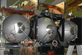
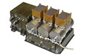
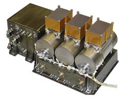
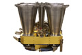
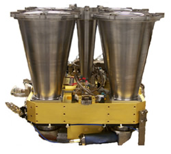
MESSENGER’s dual-mode propulsion system included a 660-newton (150-pound) bipropellant thruster for large maneuvers and 16 hydrazine-propellant thrusters for smaller trajectory adjustments and attitude control. The Large Velocity Adjust (LVA) thruster required a combination of hydrazine fuel and an oxidizer, nitrogen tetroxide. Fuel and oxidizer were stored in custom-designed, lightweight titanium tanks integrated into the spacecraft’s composite frame. Helium pressurized the system and pushed the fuel and oxidizer through to the engines.
At launch the spacecraft carried just under 600 kilograms (about 1,320 pounds) of propellant, and it used nearly 30 percent of it during the maneuver that inserted the spacecraft into orbit about Mercury. The small hydrazine thrusters played several important roles: four 22-newton (5-pound) thrusters were used for small course corrections and helped steady MESSENGER during large engine burns. The dozen 4.4-newton (1-pound) thrusters were also used for small course corrections and served as a backup for the reaction wheels that maintained the spacecraft’s orientation during normal cruise and orbital operations.
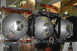
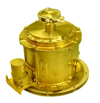
The three Titanium Main Tanks used by MESSENGER
Communications
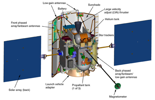
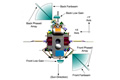
MESSENGER’s X-band coherent communications system included two high-gain, electronically steered, phased-array antennas – the first ever used on a deep-space mission; two medium-gain fanbeam antennas; and four low-gain antennas. The circularly polarized phased arrays – developed by APL and located with the fanbeam antennas on the front and back of the spacecraft – were the main link for sending science data to Earth. For better reliability the high-temperature environment antennas were fixed; they “pointed” electronically across a 45° field without moving parts, and during normal operations at least one of the two antennas pointed at Earth.
High-gain antennas sent radio signals through a narrower, more concentrated beam than low-gain antennas and were used primarily to send larger amounts of data over the same distance as a low-gain antenna. The fanbeam and low-gain antennas, also located on MESSENGER’s front and back sides, were used for lower-rate transmissions such as operating commands, status data, or emergency communications. MESSENGER’s downlink rate ranged from 9.9 bits per second to 104 kilobits per second; operators could send commands at 7.8 to 500 bits per second. Transmission rates varied according to spacecraft distance and ground-station antenna size.
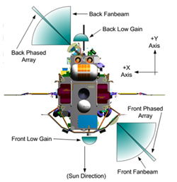
A diagram of the many antennas (high-gain phased-array antennas, medium-gain fanbeam antennas, and low-gain antennas) that the MESSENGER spacecraft uses to communicate with Earth. Additional forward and aft low-gain antennas not shown
Command and Data Handling
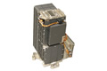
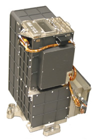
MESSENGER’s “brain” was its Integrated Electronics Module (IEM), a space- and weight-saving device that combined the spacecraft’s core avionics into a single box. The spacecraft carried a pair of identical IEMs for backup purposes; both housed a 25-megahertz (MHz) main processor and 10-MHz fault protection processor. All four were radiation-hardened RAD6000 processors, based on predecessors of the PowerPC chip found in some models of home computers. The computers, slow by current home-computer standards, were state of the art for the radiation tolerance required on the MESSENGER mission.
Programmed to monitor the condition of MESSENGER’s key systems, both fault protection processors were turned on at all times and protected the spacecraft by turning off components and/or switching to backup components when necessary. The main processor ran the Command and Data Handling software for data transfer and file storage, as well as the Guidance and Control software used to navigate and point the spacecraft. Each IEM also included a solid-state data recorder, power converters, and the interfaces between the processors and MESSENGER’s instruments and systems.
Intricate flight software guided MESSENGER’s Command and Data Handling system. MESSENGER received operating commands from Earth and could perform them in real time or store them for later execution. Some of MESSENGER’s frequent, critical operations (such as propulsive maneuvers) were programmed into the flight computer’s memory and timed to run automatically.
For data, MESSENGER carried two solid-state recorders (one backup) able to store up to 1 gigabyte each. Its main processor collected, compressed, and stored images and other data from MESSENGER’s instruments onto the recorder; the software sorted the data into files similar to how files are stored on a PC. The main processor selected the files with highest priority to transmit to Earth, or mission operators could download data files in any order the team chose.
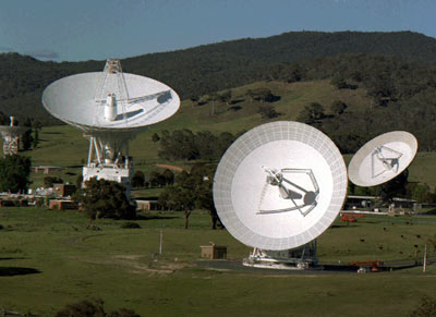
Antenna signal strength (and downlink rate) varied with spacecraft-Earth distance and ground-station antenna size. While orbiting Mercury MESSENGER stored most of its data when it was farther from Earth, typically sending only information on its condition and the highest-priority images and measurements during regular eight-hour contacts through NASA’s Deep Space Network. The spacecraft sent most of the recorded data when Mercury’s path around the Sun brought it closer to Earth.
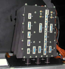
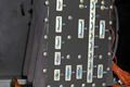
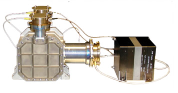
MESSENGER’s Integrated Electronics Module (IEM)

Guidance and Control
MESSENGER was well protected against the heat. It always knew its orientation relative to Mercury, Earth, and the Sun and was “smart” enough to keep its sunshade pointed at the Sun. Attitude determination – knowing in which direction MESSENGER was facing – was performed using star-tracking cameras, digital Sun sensors, and an Inertial Measurement Unit (IMU, which contained gyroscopes and accelerometers). Attitude control for the 3-axis stabilized craft was accomplished using four internal reaction wheels and, when necessary, MESSENGER’s small thrusters.
The IMU accurately determined the spacecraft’s rotation rate, and MESSENGER tracked its own orientation by checking the location of stars and the Sun. Star-tracking cameras on MESSENGER’s top deck stored a complete map of the heavens; 10 times a second, one of the cameras took a wide-angle picture of space, compared the locations of stars to its onboard map, and then calculated the spacecraft’s orientation. The Guidance and Control software also automatically rotated the spacecraft and solar panels to the desired Sun-relative orientation, ensuring that the panels produced sufficient power while maintaining safe temperatures.
Five Sun sensors backed up the star trackers, continuously measuring MESSENGER’s angle to the Sun. If the flight software detected that the Sun was “moving” out of a designated safe zone it could initiate an automatic turn to ensure that the shade faced the Sun. Ground controllers could then analyze the situation while the spacecraft turned its antennas to Earth and await instructions – an operating condition known as “safe” mode.
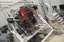
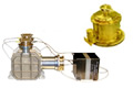
MESSENGER’s digital Sun sensors and Inertial Measurement Unit (IMU) during spacecraft development
Designed and built by the Johns Hopkins University Applied Physics Laboratory – with contributions from research institutions and companies around the world – the MESSENGER spacecraft tackled the challenges associated with orbiting Mercury. A ceramic-fabric sunshade, heat radiators, and a mission design that limited time over the planet’s hottest regions protected MESSENGER without expensive and impractical cooling systems. The spacecraft’s graphite composite structure – strong, lightweight, and heat tolerant – was integrated with a low-mass propulsion system that efficiently stored and distributed the approximately 600 kilograms (about 1,320 pounds) of propellant that accounted for 54% of MESSENGER’s total launch weight.
To fit behind the 2.5-meter by 2-meter (roughly 8-foot by 6-foot) sunshade, MESSENGER’s wiring, electronics, systems, and instruments were packed into a small frame that could fit inside a large sport utility vehicle. And the entire spacecraft was light enough for launch on a Delta II 7925-H (“heavy”) rocket, the largest launch vehicle allowed under NASA’s Discovery Program of lower-cost, space science missions.