Constructing MDIS Monochrome Mosaics
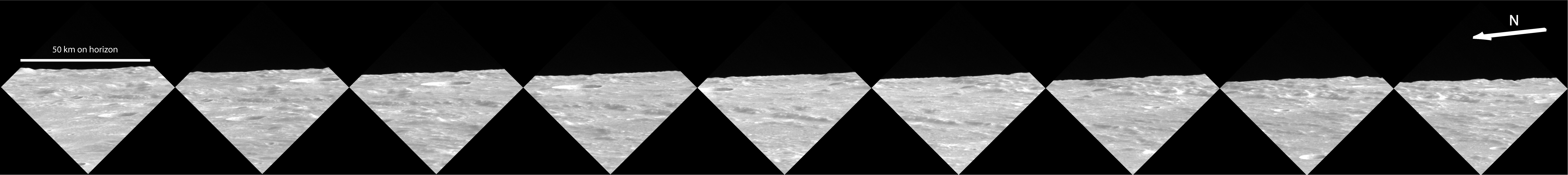
Figure 1. MDIS monochrome limb images of Mercury. The images span the coordinates 42-48°N, 186-198°E. Because each image views terrain that extends to the horizon (the planet’s limb), the scale changes markedly across each image. The scale bar indicates the scale at the horizon.
Thousands of images have been taken by the Mercury Dual Imaging System (MDIS) as a part of MESSENGER’s imaging campaign. Because no image can include Mercury’s entire surface, it is often useful to combine multiple images into a regional or global mosaic. Such mosaics are particularly important for understanding the geological context of a particular feature and for exploring Mercury’s geologic history.
Nine different monochrome limb images of Mercury’s surface, taken one after another in a single sequence by MDIS’s Narrow Angle Camera (NAC), are shown in Figure 1. Upon close inspection, these nine images all are seen to contain overlapping areas as evidenced by features that appear in adjacent images. By recognizing the common areas in the separate images, it is possible to make a “hand-laid” mosaic, one that is assembled by hand using image manipulation software (Figure 2).
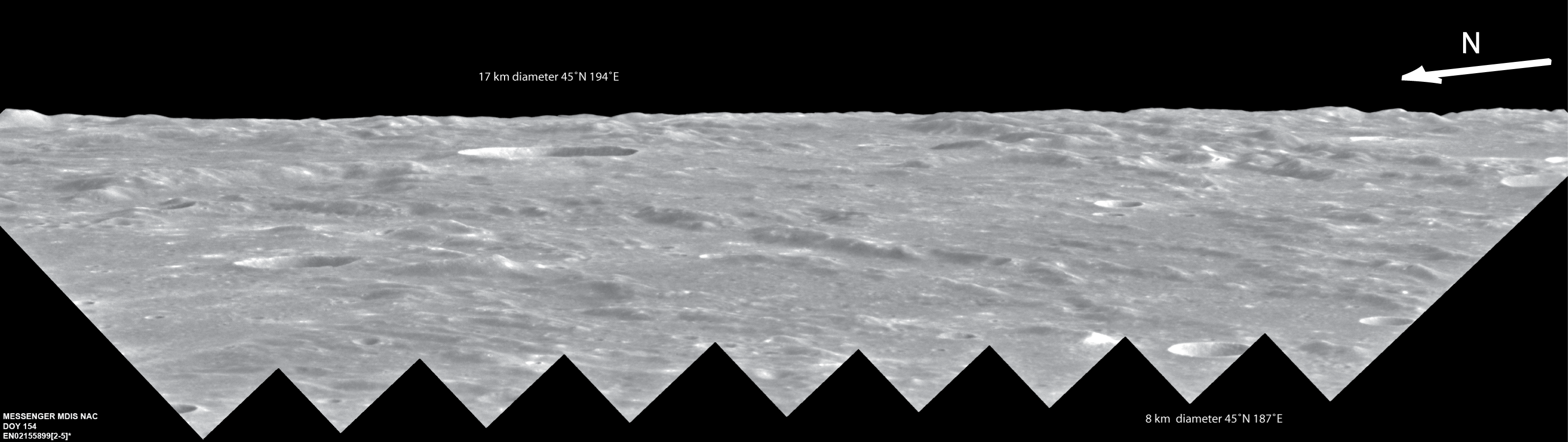
Figure 2. Hand-laid mosaic of Mercury’s surface, looking toward the horizon. This mosaic was constructed from the nine images in Figure 1. The center of this mosaic is at 46°N, 190°E.
At its simplest, mosaicking is a technique for combining images to create a larger image. The calibrated images must first be converted to a format that can be recognized by appropriate image processing software. With a hand-laid mosaic, overlapping areas are used to match adjacent images. In this manner the nine images from Figure 1 were mosaicked to create the oblique limb image of Mercury’s surface seen in Figure 2. This relatively simple hand-laid mosaic provides an interesting and beautiful perspective of the surface of Mercury looking toward the horizon, showing a landscape scarred with craters and scarps.
More complex mosaics that involve reprojection of images around a given point can yield further information about a given region. A common software package for mosaicking used by the MESSENGER team is Integrated Software for Imagers and Spectrometers (ISIS), created and maintained by the U.S. Geological Survey (USGS) Astrogeology Research Program. ISIS utilizes the latitude and longitude coordinates of each pixel to create “unsupervised mosaics” (mosaics generated using a software program rather than placed by hand). These coordinates can be computed from SPICE data. SPICE is an information system provided by NASA’s Navigation and Ancillary Information Facility (NAIF) that can be used to compute derived observation geometry, including the position and orientation of the spacecraft (MESSENGER), target body (Mercury), and the Sun. The acronym itself is indicative of some of the information SPICE provides:
S • Spacecraft: includes information about the position, or ephemeris, of a spacecraft or planetary body
P • Planet: includes information about the size, shape, and orientation of a planetary body
I • Instrument: includes information about the instrument field-of-view size, shape, and orientation
C • Camera-matrix: includes information about the orientation of a spacecraft
E • Events: includes information about science observation plans and spacecraft and instrument commands
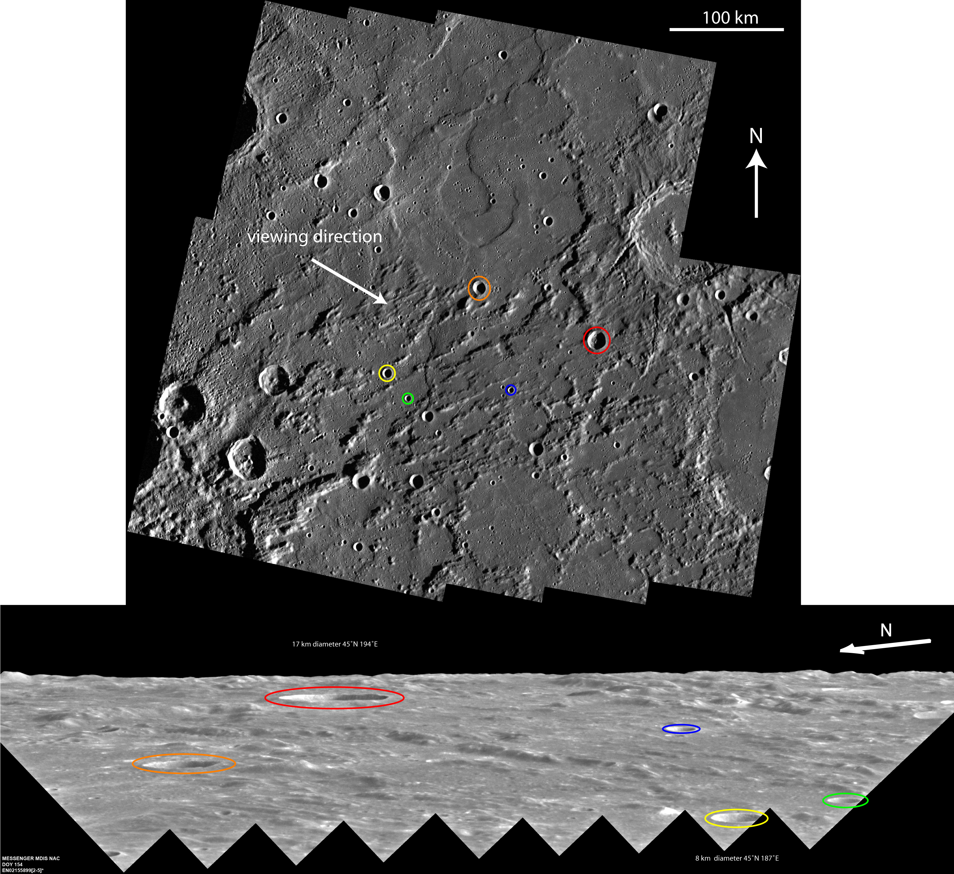
Figure 3. Correlation of features between the hand-laid limb mosaic from Figure 2 (bottom panel) and an unsupervised mosaic, an orthographic view, centered at 46°N, 190°E (top panel). The viewing direction of the lower mosaic is from the northwest.
With the incorporation of SPICE information, each pixel within an image from Mercury can be correlated to a latitude and longitude, as well as to phase, emission, and incidence angles. Once a desired map projection is specified, ISIS is able to use the latitude and longitude data from the images to be mosaicked to create a map template of the full area the images will cover. Some of the available projections include cylindrical, orthographic, polar stereographic, and sinusoidal. Once an appropriate projection is selected, each image is projected using the map template. Finally, the map-projected images are mosaicked to create the final product. Figure 3 contains an unsupervised mosaic that has been produced as described here and provides an orthographic view that includes much of the region of Mercury’s surface shown in Figure 2. The individual images of the unsupervised mosaic have also been photometrically corrected to compensate for different Sun angles at which the separate images were acquired using lighting and viewing angles provided by SPICE data along with photometric parameters derived specifically for MESSENGER images of Mercury’s surface.
A direct comparison is made between the two mosaics in Figure 3, with corresponding craters circled in the same color. The change in viewing geometry from an oblique limb view to an overhead view produces a completely different perspective that can yield more information about this portion of Mercury’s surface. It is easy to see that the viewing direction for the limb image has a major impact on how terrain location and feature orientation is perceived and how distances, accurately judged in the orthographic view, are foreshortened in the oblique limb view. The orthographic projection used for the overhead view also provides more information about the geologic context of the area. The ghost craters in the image suggest that the area has been flooded by volcanic material. What appear as rough terrain and ridges in the oblique limb view are lineated facies within the Van Eyck Formation, formed as part of the ejecta blanket of Caloris basin, which is to the lower left of the overhead-view mosaic.
As MESSENGER continues orbiting Mercury, MDIS will acquire an ever-increasing number of images. Mosaicking these images will help to reveal the nature and evolution of the surface of the innermost planet.